
Free English OMNITRONIC MP-250 (01) PDF document. Download the PDF, use the online viewer, or browse the FAQs for easy troubleshooting.
CLICK HERE TO DOWNLOAD OMNITRONIC MP-250 (01) PDF DOCUMENT
If this is not the document you want for this product, click here to see if we have any other documents for this product.
What are the key features of the OMNITRONIC MP-250 PA Amplifier?
The OMNITRONIC MP-250 is a PA mono mixing amplifier with the following features:
• PA outputs for 70 V or 100 V PA speakers or for low-impedance speakers (4-16 ohms)
• 3 microphone inputs (6.3 mm jack) with separate level controls
• Microphone input 3 with adjustable priority circuit
• 3 line inputs (stereo RCA) with separate level controls
• 1 line output (stereo RCA)
• Chime, switchable
• Treble and bass control for the output signal
• 7-fold LED level display
• Master control for the output signal
• Fan-cooled
• Protection circuits with LED indication: over current, short circuit, turn-on delay
• Rack installation
What are the functions of the front panel controls on the OMNITRONIC MP-250?
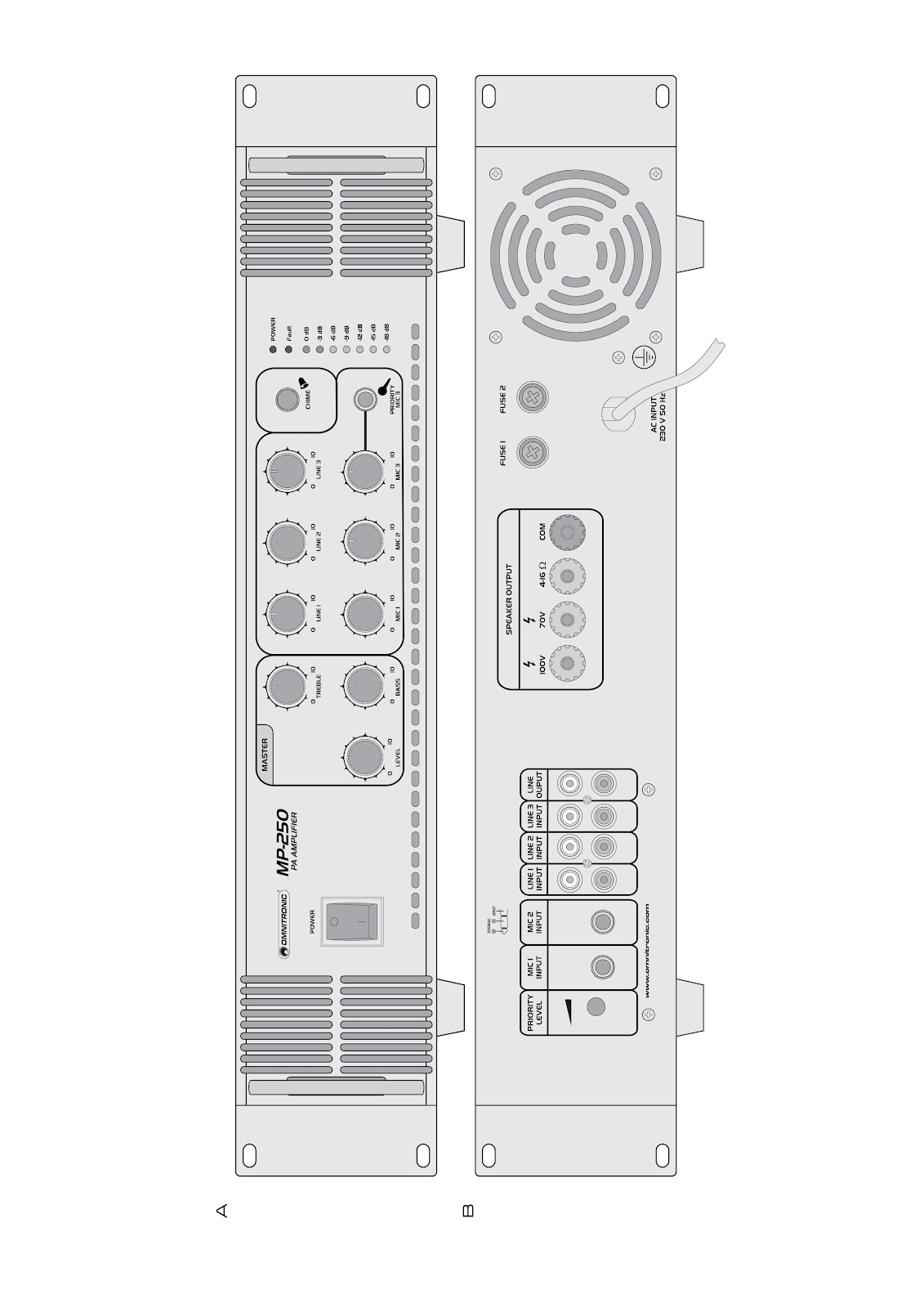
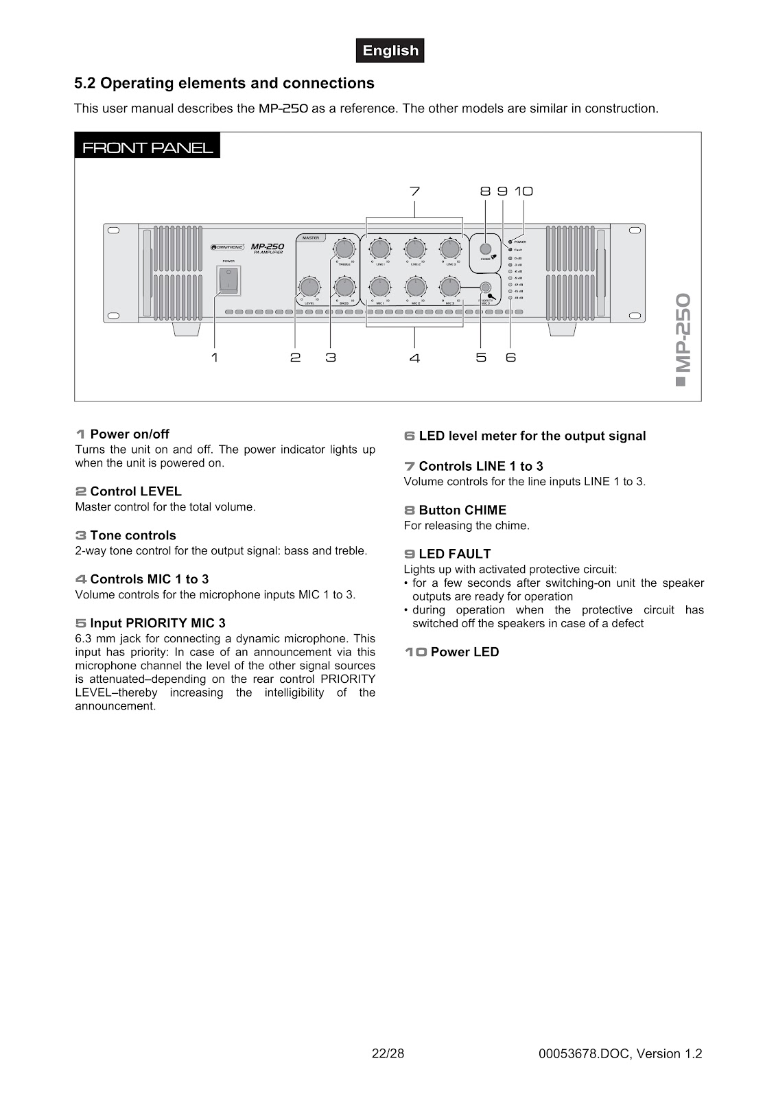
The front panel of the OMNITRONIC MP-250 features the following controls and indicators:
1. Power on/off: Turns the unit on and off. The power indicator lights up when the unit is powered on.
2. Control LEVEL: This is the master control for the total volume.
3. Tone controls: A 2-way tone control for the output signal, allowing adjustment of bass and treble.
4. Controls MIC 1 to 3: Individual volume controls for the microphone inputs MIC 1 to 3.
5. Input PRIORITY MIC 3: A 6.3 mm jack for connecting a dynamic microphone. This input has priority; when an announcement is made through this channel, the level of other signal sources is attenuated. The amount of attenuation depends on the rear control PRIORITY LEVEL, thereby increasing the intelligibility of the announcement.
6. LED level meter: Displays the level for the output signal.
7. Controls LINE 1 to 3: Individual volume controls for the line inputs LINE 1 to 3.
8. Button CHIME: Press to release the chime.
9. LED FAULT: Lights up when a protective circuit is activated. This occurs for a few seconds after switching on until the speaker outputs are ready, or during operation if the protective circuit has switched off the speakers due to a defect.
10. Power LED: Indicates that the unit is powered on.
What are the functions of the rear panel connections on the OMNITRONIC MP-250?
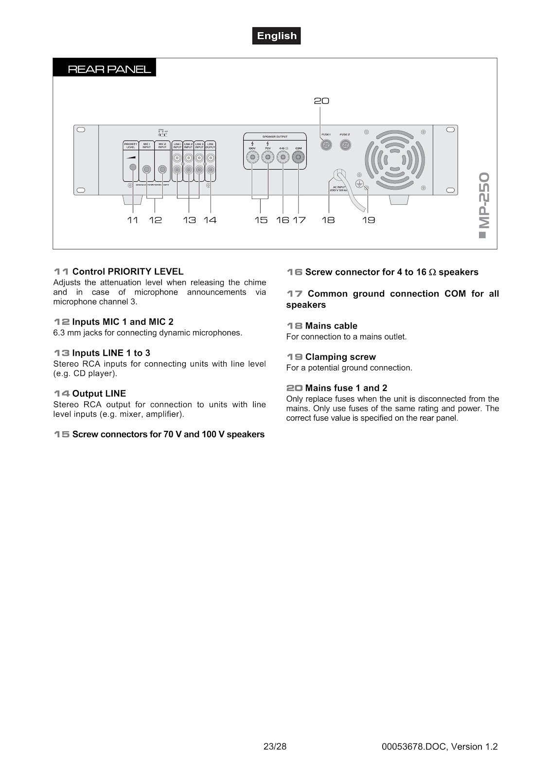
The rear panel of the OMNITRONIC MP-250 features the following connections:
11. Control PRIORITY LEVEL: Adjusts the attenuation level of other audio sources when releasing the chime or during microphone announcements via microphone channel 3.
12. Inputs MIC 1 and MIC 2: Two 6.3 mm jacks for connecting dynamic microphones.
13. Inputs LINE 1 to 3: Stereo RCA inputs for connecting units with line level signals (e.g., CD player).
14. Output LINE: Stereo RCA output for connection to units with line level inputs (e.g., mixer, another amplifier).
15. Screw connectors for 70 V and 100 V speakers: Terminals for connecting PA speakers.
16. Screw connector for 4 to 16 Ω speakers: Terminal for connecting low-impedance speakers.
17. Common ground connection COM: The common terminal for all speakers.
18. Mains cable: For connection to a mains outlet.
19. Clamping screw: For a potential ground connection.
20. Mains fuse 1 and 2: Fuses for the mains power. Only replace with fuses of the same rating and power, as specified on the rear panel.
How should I install the OMNITRONIC MP-250 into a rack?
The OMNITRONIC MP-250 amplifier is built for 483 mm (19″) racks. Follow these guidelines for proper installation:
• Use a double-door rack where both the front and rear panels can be opened. The rack should be provided with a cooling fan.
• Ensure there is enough space around the device so that heated air can pass. Steady overheating will damage your device.
• Fix the amplifier with four M6 screws in the rack.
• If several devices are installed, leave at least 1 unit (1 U) of space between them.
• When mounting, be careful. Place the heaviest devices, like this amplifier, into the lower part of the rack.
• Fastening the amplifier with only four screws on the front panel is not sufficient. For safety, additional fastening using ground and side bars is necessary.
• If racks are to be transported or used for mobile applications, fasten the devices additionally by connecting the rear brackets with the side or ground bars of the rack. This prevents the amplifier from being pushed backward, as the front panel alone is not designed to absorb acceleration forces during transportation.
How do I connect speakers to the OMNITRONIC MP-250?
You can connect either PA speakers with 70 V and 100 V audio transformers or 4-16 Ω speakers. High voltage is present at the terminals when using PA systems, so installation should be done by skilled personnel only, with the amplifier turned off.
1. PA Speakers (70 V / 100 V):
Connect PA speakers to the terminals COM (negative pole) and 70V or 100V (positive pole). The total load must not exceed 250 WRMS for the MP-250, otherwise the amplifier may be damaged by overload.
2. Low-Impedance Speakers (4-16 Ω):
Connect low-impedance speakers to the terminals COM (negative pole) and 4-16 Ω (positive pole).
3. Polarity:
When connecting, observe the correct polarity (positive and negative connections). The positive connection of the speaker cables is always specially marked.
The input impedance of the speaker systems should at least be the same or even higher than the output impedance of the amplifier.
Example for the calculation of speakers/impedance when using low-impedance speakers:
| Number of speakers | Impedance |
|---|---|
| 1 speaker at 8 Ω | 8 Ω |
| 2 speakers at 8 Ω each | 4 Ω (parallel) |
| 2 speakers at 8 Ω each | 16 Ω (in line) |
| 3 speakers at 8 Ω each | 2.66 Ω (parallel) |
| 3 speakers at 8 Ω each | 24 Ω (in line) |
| 4 speakers at 8 Ω each | 2 Ω (parallel) |
What should I consider when choosing speaker cables for the OMNITRONIC MP-250?
When using low-impedance speakers, consider the following for your speaker cables:
• Speaker systems must only be connected via sufficiently dimensioned cables. Too thin cables lead to cable heatup or enormous power loss and loss in sound quality.
• For all speaker systems up to 400 Watts, we recommend a cable diameter of 2.5 mm²; for all other speaker cables, use 4 mm².
• A high damping factor of your amplifier supplies a clear sound reproduction. Unnecessarily long and thin cables will influence the damping factor and thus the low frequencies in a negative way. In order to safeguard good sound quality, the damping factor should lie around 50. The longer a cable has to be, the thicker it should be. In this respect, a damping factor of 200 will be reduced to 47 (8 ohms) when using a 10 m long, 2.5 mm² speaker cable. The power loss at 8 ohms is 1.63 % and at 4 ohms 3.25 %.
What are the general guidelines for installing cables with the OMNITRONIC MP-250?
Follow these general guidelines when installing cables:
• Always treat cables carefully and protect them from damages during transportation.
• Install cables always in a structured way and protect them from damage.
• Cables must be installed in a way that no person can stumble over them. Always fix cables with an appropriate tape.
• Cables should be installed directly (no loops, S-shaped overlengths).
• Always install audio cables far away from power cables (never closely parallel).
• Never put heavy objects like speaker systems, flightcases etc. on cables.
• Never operate cables that are wound up.
How do I connect the OMNITRONIC MP-250 to mains power?
After connecting all other devices, connect the OMNITRONIC MP-250 to a mains outlet (230 V AC, 50 Hz ~) with the mains cable. The earth connection must be used. The occupation of the connection cables is as follows:
| Cable | Pin | International |
|---|---|---|
| Brown | Live | L |
| Blue | Neutral | N |
| Yellow/Green | Earth | ⏚ |
If the device will be directly connected with the local power supply network, a disconnection switch with a minimum opening of 3 mm at every pole has to be included in the permanent electrical installation. The device must only be connected with an electric installation carried out in compliance with the IEC standards. The electric installation must be equipped with a Residual Current Device (RCD) with a maximum fault current of 30 mA.
What is the correct procedure for operating the OMNITRONIC MP-250?
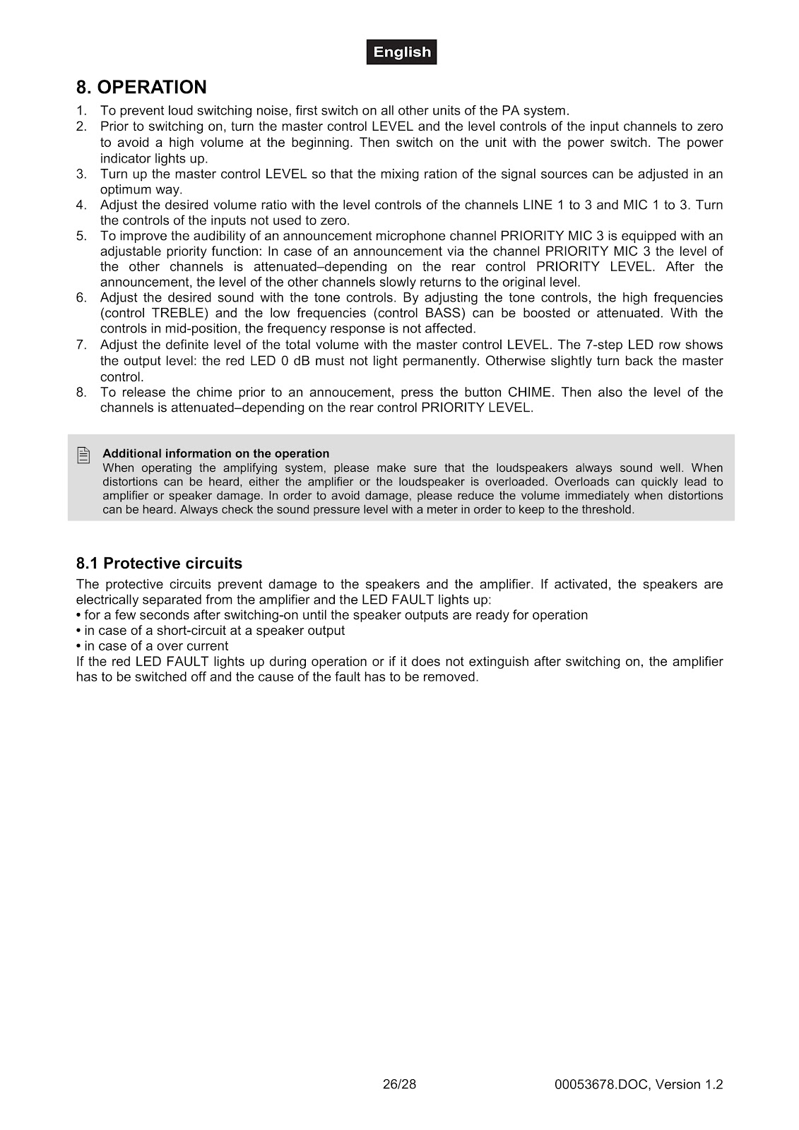
Step 1. To prevent loud switching noise, first switch on all other units of the PA system.
Step 2. Prior to switching on the amplifier, turn the master control LEVEL and the level controls of the input channels to zero to avoid a high volume at the beginning. Then switch on the unit with the power switch. The power indicator lights up.
Step 3. Turn up the master control LEVEL so that the mixing ratio of the signal sources can be adjusted in an optimum way.
Step 4. Adjust the desired volume ratio with the level controls of the channels LINE 1 to 3 and MIC 1 to 3. Turn the controls of the inputs not used to zero.
Step 5. To improve the audibility of an announcement, microphone channel PRIORITY MIC 3 is equipped with an adjustable priority function. In case of an announcement via this channel, the level of the other channels is attenuated depending on the rear control PRIORITY LEVEL. After the announcement, the level of the other channels slowly returns to the original level.
Step 6. Adjust the desired sound with the tone controls. By adjusting the tone controls, the high frequencies (control TREBLE) and the low frequencies (control BASS) can be boosted or attenuated. With the controls in mid-position, the frequency response is not affected.
Step 7. Adjust the definite level of the total volume with the master control LEVEL. The 7-step LED row shows the output level: the red LED 0 dB must not light permanently. Otherwise, slightly turn back the master control.
Step 8. To release the chime prior to an announcement, press the button CHIME. Then also the level of the channels is attenuated, depending on the rear control PRIORITY LEVEL.
What are the protective circuits on the OMNITRONIC MP-250 and what does the FAULT light indicate?
The protective circuits prevent damage to the speakers and the amplifier. If activated, the speakers are electrically separated from the amplifier and the LED FAULT lights up in the following situations:
• For a few seconds after switching-on until the speaker outputs are ready for operation.
• In case of a short-circuit at a speaker output.
• In case of an over current.
If the red LED FAULT lights up during operation or if it does not extinguish after switching on, the amplifier has to be switched off and the cause of the fault has to be removed.
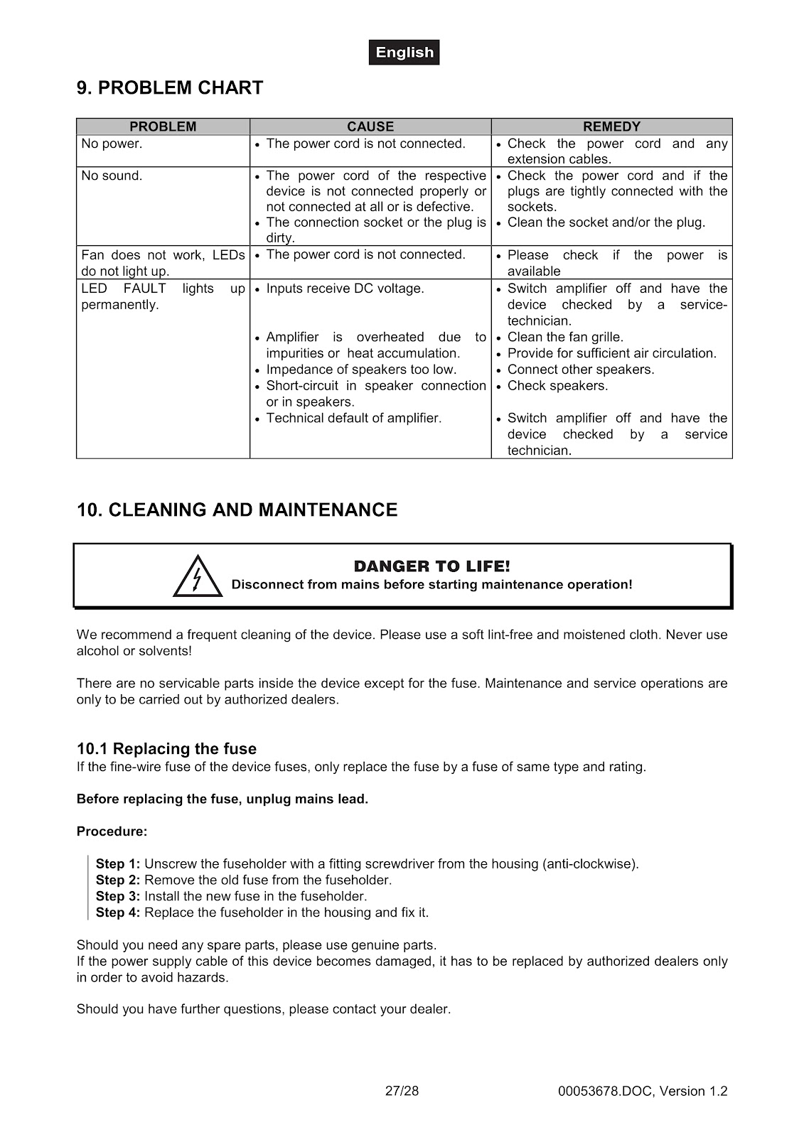
How can I troubleshoot common problems with the OMNITRONIC MP-250?
| Problem | Cause | Remedy |
|---|---|---|
| No power. | The power cord is not connected. | Check the power cord and any extension cables. |
| No sound. | • The power cord of the respective device is not connected properly or not connected at all or is defective. • The connection socket or the plug is dirty. |
• Check the power cord and if the plugs are tightly connected with the sockets. • Clean the socket and/or the plug. |
| Fan does not work, LEDs do not light up. | The power cord is not connected. | Please check if the power is available. |
| LED FAULT lights up permanently. | • Inputs receive DC voltage. • Amplifier is overheated due to impurities or heat accumulation. • Impedance of speakers too low. • Short-circuit in speaker connection or in speakers. • Technical default of amplifier. |
• Switch amplifier off and have the device checked by a service technician. • Clean the fan grille. • Provide for sufficient air circulation. • Connect other speakers. • Check speakers. • Switch amplifier off and have the device checked by a service technician. |
How do I clean the OMNITRONIC MP-250?
Before any maintenance, disconnect the OMNITRONIC MP-250 from the mains. We recommend a frequent cleaning of the device. Please use a soft lint-free and moistened cloth. Never use alcohol or solvents.
How do I replace the fuse on the OMNITRONIC MP-250?
If the fine-wire fuse of the device fuses, only replace the fuse by a fuse of the same type and rating. Before replacing the fuse, unplug the mains lead.
Procedure:
Step 1: Unscrew the fuseholder with a fitting screwdriver from the housing (anti-clockwise).
Step 2: Remove the old fuse from the fuseholder.
Step 3: Install the new fuse in the fuseholder.
Step 4: Replace the fuseholder in the housing and fix it.
What are the technical specifications for the OMNITRONIC MP-250?
| Specification | MP-250 |
|---|---|
| Power supply: | 230 V AC, 50 Hz ~ |
| Output power: | 250 WRMS |
| Output type: | 70 V, 100 V or 4-16 Ω |
| Microphone input: | 5 mV, 600 Ω |
| Line input: | 300 mV, 10 kΩ |
| Output: | screw connectors |
| Frequency range: | 80 Hz – 14 kHz |
| Distortion: | 0.5 % (1 kHz) |
| S/N ratio: | 85 dB (line), 75 dB (mic) |
| Protection: | over current, short circuit, turn-on delay |
| Indicators: | power, fault, level |
| Dimensions: | 483 x 400 x 88 mm |
| Weight: | 11.5 kg |
How to use the PDF below:
* Touchscreen: Swipe up/down with-in the PDF to scroll and pinch or spread with two fingers to zoom.
* Mouse: While your mouse is hovering over the PDF, use the mouse wheel to scroll and click on the – / + buttons at the bottom of the PDF to zoom.


CLICK HERE TO DOWNLOAD OMNITRONIC MP-250 (01) PDF DOCUMENT